|
|
Max Charge Advanced Programming - Belt Load / Amp Manager |
|
All of the following information is to be used as a guide.
Refer to your manufacturer's operator's manual for the equipment that you have installed for the proper detailed instructions.
Special Note:
On the initial MC regulator setup, You need to
Verify and Set your
Battery Type
bA (?AgL), and
Program the following suggested changes to the following parameters as follows: Bulk Voltage -
bv (14.2)
, BV Time -
b1c (6 MIN)
, Absorb Time -
A1c(6 MIN)
, Float Volts -
Fv (13.2)
, and the Max Alt Temp -
AL1 (Range between 82 to 90).
In addition during non-standard cruising (special situations) you may need to enter the belt load manager program function.
As an example, HVAC when operating in the HEATING mode, consumes 1/3 (132%) more power than when in the cooling mode. In addition, as the seawater
gets colder, there is less heat available and heating performance drops. Full heating capacity is only available with water temperatures above 60°F. Heating capacity drops to 50% in
40°F water. Manufacturers do not allow operation below 40°F - Operation at these temperatures is not permitted due to permanent equipment damage. Depending on the air and water
temperature, and due to its low efficiency in cold weather, the HVAC compressor is usually in a constant run mode requiring an inordinate amount of
power deeply draining battery resources and rapidly. If dedicated heaters (propane, diesel, ...) are not installed, shore power should be sought and electric space heaters
utilized. Regardless of reason, if the battery resources are deeply discharged, the amp manager function (explanation follows) should be applied to
allow an extended reduced output charge rate [MC614 - function bEL (Belt Load Manager) value B9 results in a 45% reduction, older MC612 - function AP
(amp manager) value 50%] to prevent damage to any alternator used. If you are using a shore power charger to restore a deeply discharged battery bank, this step may be avoided.
With a severely discharged battery bank, it is highly recommended to use shore power for recharging because a complete recharge cycle from a severely discharged state may require over
48 hours to complete properly.
NOTE: The following is Applicable to the MC-614 Regulator
Older MC-612 Regulator Advanced Programming Instructions follows below after the MC-614 instructions
Activate (Turn On) your regulator specific to your installation
[on/off switch, ignition switch, engine start - if an oil pressure switch is used, ...]
 |
|
Special Note: Although it was not previously mentioned in the Max Charge Regulator installation and Operator's manual, ZRD discovered
that the
battery voltage used to program the Max Charge regulator must be in excess of 12.5 Vdc or else any modifications (
changes) that are made will not be captured or saved - This is even though the regulator says that the changes were saved (unit displays PRO followed by SAV).
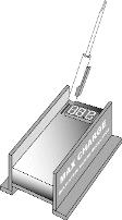
In addition to the regulator's short display, a longer, more in-depth display is available when the magnetic reed switch located next to the LED display is activated with
a short touch of the magnetic programming screwdriver as shown. When activating the reed switch, place the magnetic tip of the screwdriver against the epoxy potting at one
or the other end of the reed switch located on the circuit board in the upper left corner of the regulator. |
Older (Previous) MC-612 Regulator Advanced Programming Instructions
 |
|
To access Advanced Programming Levels:
1. Activate your regulator specific to your installation (on/off switch, ignition switch, engine start - if an oil pressure switch is used, ...)
2. Once the regulator is activated and the numeric display is illuminated, activate the regulator's reed switch with the supplied magnetic screwdriver. Continue
to hold the magnetic tip of the screwdriver against the reed switch. The display will indicate entry into the Basic Programming mode with the code "PRO". As soon
as the "PRO" display is indicated, release the switch by removing the magnet from the magnetic reed switch.
3. The regulator's display will indicate entry to the advanced programming mode with the "PRA" code.
4. Once in "PRA" mode, the regulator's display will scroll through the advanced programming options indicated in the chart shown on the left. You will have three
opportunities to make adjustments.
5. When the desired Amp Manager code is shown (below),
Activate and HOLD the magnetic reed switch with the magnetic programming tool. The display will indicate the set value for that mode.
As you continue to hold the magnet to the reed switch, the various programming values will be shown on the display. As soon as your desired value is indicated in the display,
release the switch by removing the magnet from the magnetic reed switch.
 |
Additional details for Advanced Programming Modes:
• DLc -- Start Delay. Controls the amount of time from regulator activation to start of charging. Factory preset at one
second. Can be adjusted to a maximum of 200 seconds. To reverse direction of scroll, release magnet and wait for LED
to display dlc code. Re-activate switch with magnet and release when desired value is indicated.
• Cl -- Compensation Limit. Controls the maximum limit of allowable system voltage. Starts at value set by battery
program currently in use. Adjustment spans from 14.1 to 15.9 volts. To reverse direction of scroll, release magnet and
wait for LED to display Cl code. Re-activate switch with magnet and release when desired value is indicated.
• Bu -- Bulk voltage adjustment. Controls the maximum limit of allowable bulk voltage. Starts at value set by battery
program currently in use. Adjustment spans from 14.1 to 14.8 volts. To reverse direction of scroll, release magnet and
wait for LED to display bu code. Re-activate switch with magnet and release when desired value is indicated.
• B1c -- Bulk time adjustment. Controls the minimum time period for non-calculated bulk charging. Standard value set
by battery program selected. Adjustment spans in tenths of hours from 12 minutes to six hours. To reverse direction
of scroll, release magnet and wait for LED to display B1c code. Re-activate switch with magnet and release when
desired value is indicated.
• Au -- Bulk voltage adjustment. Controls the maximum limit of allowable bulk voltage. Starts at value set by battery
program currently in use. Adjustment spans from 13.5 to 14.8 volts. To reverse direction of scroll, release magnet
and wait for LED to display au code. Re-activate switch with magnet and release when desired value is indicated.
• A1c -- Bulk time adjustment. Controls the minimum time period for non-calculated absorption charging. Standard
value set by battery program selected. Adjustment spans in tenths of hours from 12 minutes to six hours. To reverse
direction of scroll, release magnet and wait for LED to display a1c code. Re-activate switch with magnet and release
when desired value is indicated.
• Fu -- Bulk voltage adjustment. Controls the maximum limit of allowable float voltage. Starts at value set by battery
program currently in use. Adjustment spans from 13.0 to 13.8 volts. To reverse direction of scroll, release magnet
and wait for LED to display au code. Re-activate switch with magnet and release when desired value is indicated.
• F1c -- Bulk time adjustment. Controls the minimum time period for non-calculated float charging. Standard value
set by battery program selected. Adjustment spans in tenths of hours from 12 minutes to six hours. To reverse direction
of scroll, release magnet and wait for LED to display a1c code. Re-activate switch with magnet and release when
desired value is indicated.
• AP -- Amp Manager. Governs the maximum field potential percentage allowed. Can be used to de-tune alternator output.
When "AP" is displayed on the LED, activate switch. "OFF" code will be displayed. Release switch. When "AP" is indicated,
re-activate and hold switch with magnetic tool. Display will decrement through percentage values (98, 96, 94, and so on).
Release when the desired percentage is indicated.
• Eu -- Equalization voltage adjustment. Governs equalization/conditioning voltage. Starts at value set by battery program
currently in use. Adjustment spans from 14.8 to 16.5 volts. To reverse direction of scroll, release magnet and wait for LED to
display eu code. Re-activate switch with magnet and release when desired value is indicated.
• E1c -- Equalization time adjustment. Controls the time period for equalization/conditioning charging. Adjustment spans in
tenths of hours from 30 minutes to three hours. To reverse direction of scroll, release magnet and wait for LED to display e1c code.
Re-activate switch with magnet and release when desired value is indicated.
• FBA -- Controls the criteria the regulator uses to determine how hard the alternator has to be working to stay in calculated
bulk charging mode. Factory set at 75% field output. Raising "FBA" shortens calculated bulk charge time. Lowering "FBA" increases
calculated bulk charge time. Adjusted in 2% increments. Span of adjustment is 16% to 96%. To reverse direction of scroll, release
magnet and wait for LED to display "FBA" code. Re-activate switch with magnet and release when desired value is indicated.
• FFL -- Controls the criteria the regulator uses to determine how hard the alternator has to be working to stay in calculated
absorption charging mode. Factory set at 75% field output. Raising "FFL" shortens calculated absorption charge time. Lowering "FFL"
increases calculated absorption charge time. Adjusted in 2% increments. Span of adjustment is 16% to 96%. To reverse direction of scroll,
release magnet and wait for LED to display "FFL" code. Reactivate switch with magnet and release when desired value is indicated.
• AL1 -- Controls the setpoint at which point field current is reduced when the the alternator temperature sensor indicates an
over-temp condition at the alternator. Requires temperature sensor installation. Adjustable from 30 to 125 degrees C.


