The formula below shows the basic relationship of the main factors in an electrical circuit. It is known as Ohm's Law. Ohm's Law in more exact definition deals with the relationship between voltage and current in an ideal conductor. This relationship states that: The potential difference (voltage) across an ideal conductor is proportional to the current through it.

Explanation of Terms:
V - stands for voltage, the unit is the Volt.
I - stands for current, the unit is the Amp.
R - stands for resistance/impedance, the unit is the Ohm.
Joule's Law (below) is derived (using variable substitution) from Ohm's basic formula using a new measurement that includes the value for power. It should be apparent why the term volt-amp means watt.

Explanation of Newest Term:
P - stands for power, the unit is the Watt.

Placing Ohm's law into Joule's Law (using algebraic substitution), one can calculate the "power loss" due to the transmission in the wiring. The second part of the same equation after additional algebraic substitutions (no need to go in detail here) allows one to simply measure the initial starting voltage at the source supplying power and also measure the voltage at the load end. The net difference between the two measured voltages is what is entered into the value for V. in the second equation. The value for R is dependent on the wire used for the transmission. For copper wire at 20 degrees C, the FAQ on wire size (Click to view) has many values for R. As an example, if during installation a round trip wire run is long, and undersized wire is used, many watts of output are converted to heat in the wire and "lost" during transmission. Factually, Power (watts or volt-amps) is never lost, but its form may change during transmission. The net result is that it appears that amps get "lost" and disappear. You should now understand that the value of I (amount of current transformed) is desired to be as close to zero (0) as possible. For this to happen, the voltage drop needs to be as close to zero as possible (per Ohm's Law, Direct Proportional Relationship). To accomplish this, the resistance needs to be as close to zero as possible. This is always achieved by properly sizing wiring.
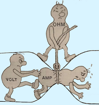
Simplified explanation of Current (amperage), Force (voltage), Resistance (ohms), & Power (wattage),
|
A plumbing/water hose analogy may assist one to more easily understand the physics involved above.
Voltage is equivalent to the water pressure, Current is equivalent to the mass (volume) of water flowing, and Resistance is equivalent to the size (diameter) of the pipe the water is travelling through. If the water pressure (voltage) increases, more water (amps) will come out of the hose (resistance). The same is true of an electrical system: Increasing the voltage will make more current flow. If you increase the diameter of the hose and all of the fittings, this also makes more water come out of the hose. This is like using a larger size (gauge) wire decreasing the resistance in an electrical system, which increases the current (amperage) flow. The total power is the voltage pushing (times) the amps going through. |
 |
Notes:
The circuit diagram was drawn to allow the user to visualize the wiring as either a single wire or a pair (or more) of parallel wires in order to understand the decrease resistance discussion. Also did you notice how the Voltage ("battery") was labeled. Many were taught (incorrectly) the opposite years ago, but in fact electrons leave from the negative terminal. Electrons are a negative charge, and they (as ELECTRON CURRENT) flow from the negative terminal of a battery, through the circuit, and back into the positive terminal.