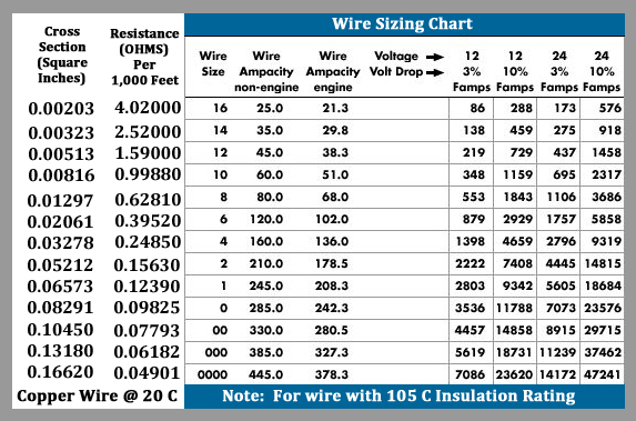
Below is a chart that shows the proper wire sizing for the current flowing in your vessel.
Ensure you verify requirements and check with properly authorized electricians for installations.

Ensure you verify requirements and check with properly authorized electricians for installations.

Voltage Drop - Calculated from source to supplied load (+ Back) using the following formula. This is the actual true total of FOOT-AMPS.
[ (Round Trip Distance-feet * Specific Resistance of Wire Type and Size used * Amp Load) / 1000 ]
Example [ (80 * 0.04901 * 200) / 1000 ] = 0.78416 volts
The above example is using a ZRD 24Vdc-400amp DC Genset, installed with 0000 battery cable having a 40' one-way distance run from the Genset Dual Output to the Battery Bus Bar. This solution has a 0.78 voltage drop. This is within the highest quality standard - Lowest 3% [ (0.78416/28.2) = 2.78% ] drop.
Depending on the wiring plan designed/utilized, the installation technician always needs to pay attention. Dual, Triple, or more wiring (in parallel) may be required to carry the electrical current (load) properly. This is accentuated with long cable runs, low voltage, and highest output. (Click to read the Primary Electrical Formulas FAQ to understand the underlying physics in more detail)
Note:
We discovered that depending on distance, a wire size (awg) of 8, 6, or LARGER may be required as a minimum for Refrigeration, Radar, or HF Radio installations. Proper wire sizing prevents system shutdown on start up due to too high a resistance being created in an undersized wire. Additionally, even if the equipment works with fine a fully charged (12.8 Vdc for 12 a volt system) battery bank, it may not work as that same battery bank is used and its voltage drops. Again, depending on distance and wire size, you may start off with a 0.5 to 2.0 Voltage drop due to a long wire run with undersized wiring! One would normally think that 10 awg wire (60 amps usable, outside of engine spaces) would be sufficient for a 10-15 amp loaded circuit. However, the 348 famps limit will easily be exceeded with a moderate (over 11 feet) circuit run. Remember to use the round trip, not one way, distance when calculating Famps.
Summary of items to consider when using the chart above - What wire size should I use?
1. Calculate the maximum sustained amperage of the circuit. Measure the length of the circuit from the power source to the load and back.
2. Decide whether the circuit runs in an engine space or non-engine space. Engine spaces are assumed to be at 50 degrees C, non-engine spaces are assumed to be at 30 degrees C.
3. Multiply the maximum current times the length of the circuit to calculate Famps (Feet x amps).
4. Base the wire on either the 3% or 10% voltage drop. In general, items which affect the safe operation of the boat and its passengers (running lights, bilge blowers, electronics and distribution panel supply circuits) use 3%; all other loads use 10% (cabin lights, pumps).
5. Starting in the column which has the right voltage and voltage drop shown at the top, run down the list of numbers until arriving at a value which is greater than the calculated Famps. Move left to the Ampacity column to verify that the total amperage of the circuit does not exceed the maximum allowable amperage of the wire size for that row. If it does, move down until the wire ampacity exceeds the circuit amperage. Finally, move left to the wire size column to select the wire size.
Examples
1. A 12 volt system at 10% drop with a 40' circuit x 45 amps = 1800 Famps. A wire size of 8 is required.
2. A 24 volt system at 3% drop with a 10' circuit x 120 amps = 1200 Famps. A wire size of 6 is required.
Some sample (rough, not absolute) Guidance for DC wiring on most cruising vessels
• Any wire means Positive or Negative (+ or -)
• xx/yy = (means) probably Ok / preferred (what ZRD would do)
• 00/0000 - Any wire that connects batteries should be at least this size (normally)
• 00 - Any wire that powers the engine starter should be at least this size
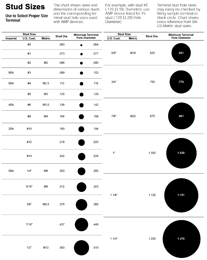
• 00 or 0000 - Any wire connected to bus bar main studs
• 06 up to 01/00 - Shore Charger output main power cables
• 04 up to 00/0000 - Alternator output main power cables - size is dependent on Output Amperage
• 10/08 - DDC main power cables
